



Dynamic Contact Resistance Testing During Circuit Breaker Closing
Dynamic Contact Resistance Testing During Circuit Breaker Closing
Dynamic Resistance Measurement (DRM) during circuit breaker closing is a valuable diagnostic method for medium- and high-voltage circuit breakers. It helps technicians understand how electrical conduction is established during the closing operation, how the contacts behave at first touch, whether contact bounce occurs, and whether the final contact resistance stabilizes correctly.
This article explains why DRM during closing should be considered together with DRM during opening, especially in advanced circuit breaker test procedures involving timing, travel, contact resistance test, and dynamic contact resistance analysis.
1. Purpose of DRM during circuit breaker closing
The purpose of DRM during closing is to evaluate the electrical behavior of the circuit breaker while the contacts are moving toward the closed position. Unlike a static contact resistance test, which only measures the final closed condition, DRM provides a dynamic view of the closing sequence.
During the closing operation, the test can reveal:
- the instant of first electrical touch;
- the behavior of the arc contact or arcing contact;
- the transfer of conduction from arc contact to main contact;
- contact bounce or momentary re-openings;
- high final contact resistance;
- incorrect operation of pre-insertion resistors, where applicable;
- correlation between electrical behavior, contact travel and breaker timing.
2. DRM test connection principle
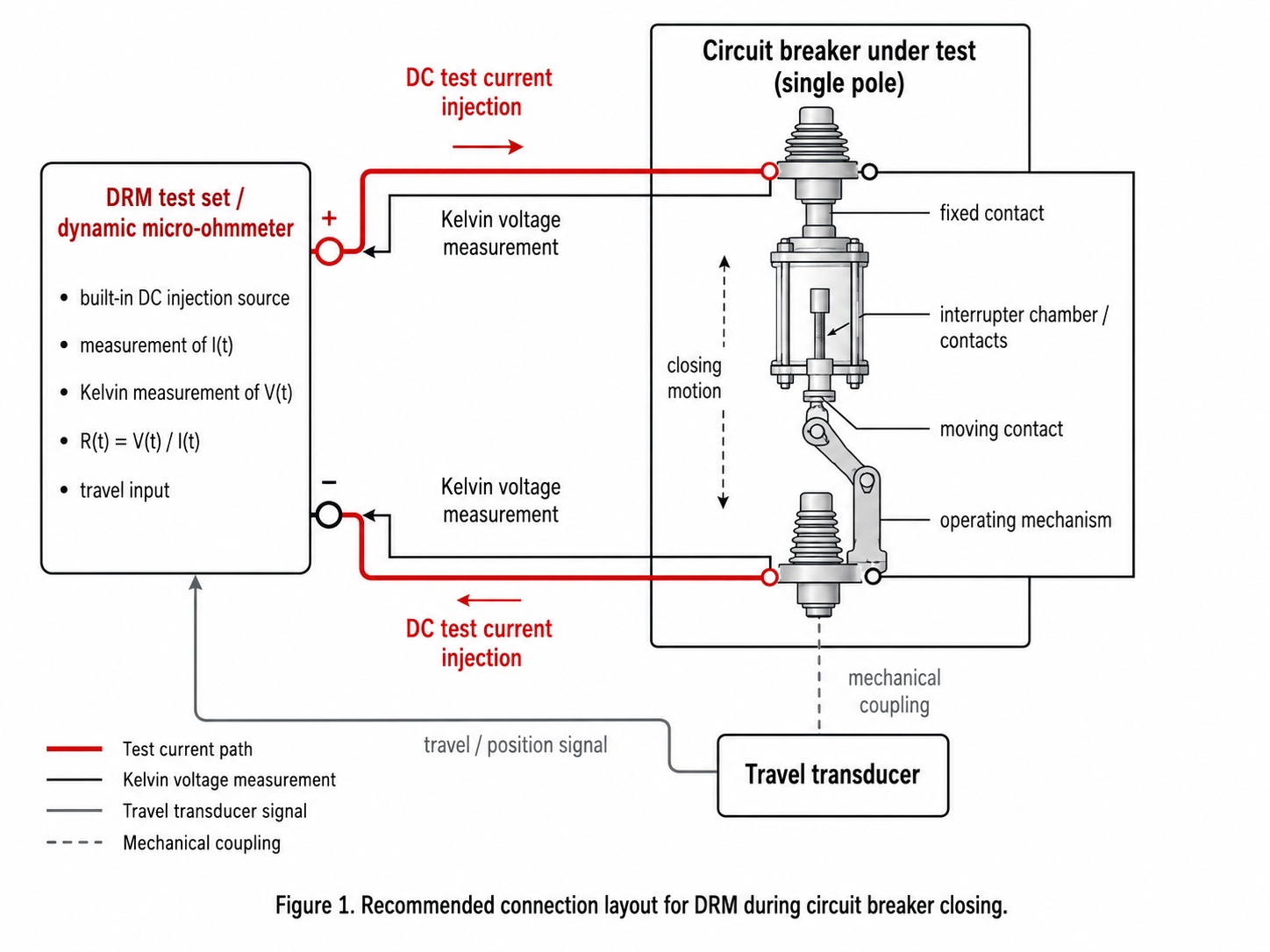
In many DRM test sets, the DC current source, voltage measurement channels, current measurement and acquisition functions are integrated in the same instrument. The equipment injects DC current through the circuit breaker and measures voltage using Kelvin connections. From these signals, the dynamic resistance is calculated as:
R(t) = V(t) / I(t)
The travel transducer is mechanically coupled to the breaker mechanism or moving contact linkage. Its electrical signal is connected to the DRM acquisition input. The transducer must not be interpreted as part of the main current circuit.
3. Why perform DRM during closing and not only during opening?
DRM during opening and DRM during closing provide complementary information. Opening DRM mainly shows how the contacts separate and how current transfers toward the arcing contacts. Closing DRM shows how conduction is established, how contacts impact, whether bounce occurs, and whether the main contact reaches a stable low-resistance condition.
Measuring only during opening may miss defects that appear during the closing operation. Examples include unstable first touch, excessive contact bounce, poor damping, insufficient final pressure, irregular transfer to the main contact, and incorrect pre-insertion resistor timing.
| Aspect assessed | Opening DRM | Closing DRM |
|---|---|---|
| Main phenomenon | Contact separation and current transfer toward arcing contacts. | Establishment of conduction: first touch, arc contact, overlap and main contact. |
| Defects more visible | Arc contact wear, irregular separation and opening synchronism issues. | Contact bounce, irregular impact, poor final pressure, unstable transition and PIR timing issues. |
| Mechanical information | Relationship between separation, speed and arcing-contact conduction duration. | Relationship between approach, impact, bounce, damping and final stabilization. |
| Risk if not measured | A separation-related anomaly may be missed. | An unstable closing may be missed even if opening appears acceptable. |
4. Interpretation of a healthy DRM closing curve
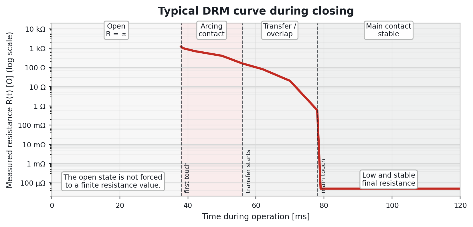
A healthy DRM closing curve usually contains four main zones:
- Open circuit: the circuit breaker is open and there is no conductive path.
- First touch: the first measurable electrical contact appears, normally through the arc contact.
- Transfer / overlap: conduction transfers progressively toward the main contact.
- Final closed condition: resistance stabilizes at a low and repeatable value.
When the circuit breaker is open, resistance should be represented as R = ∞ or out of measurable range. It should not be forced to an arbitrary finite value such as 106. The resistance curve should start only when a conductive path exists.
5. Reading the DRM curve zones
| Zone | Phenomenon | Units / representation | Expected behavior | Indication if abnormal |
|---|---|---|---|---|
| Open | No conductive path exists. | R = ∞ / out of range. Time in ms. | No finite resistance value is assigned. | Unexpected leakage, severe contamination or test connection issue. |
| First touch | Initial contact, normally via arc contact. | Ω, mΩ or µΩ depending on method and resolution. | Clear and repeatable resistance drop. | Delay, missing drop, unstable event or excessive scatter. |
| Transfer / overlap | Transfer toward main contact. | R(t) in Ω, mΩ or µΩ; duration in ms. | Consistent transition without unjustified spikes. | Misalignment, bounce, irregular wear or poor synchronism. |
| Final closed | Conduction through main contact. | Usually µΩ or mΩ. | Low, stable and repeatable resistance. | Dirty contact, insufficient pressure, corrosion, damage or poor Kelvin connection. |
6. Typical anomalies detected during closing DRM
6.1 Contact bounce
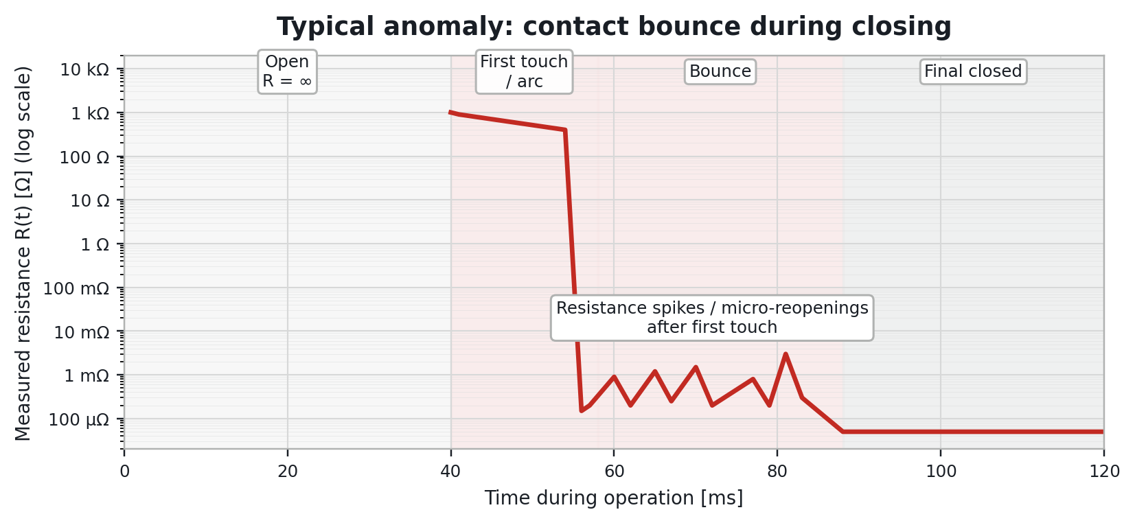
Contact bounce appears as resistance spikes or momentary re-openings after first touch. It may be caused by poor damping, mechanism fatigue, incorrect closing speed, mechanical adjustment problems or pole synchronism issues.
This is one of the most important reasons for performing DRM during closing, because contact bounce may not be visible when only opening DRM is performed.
6.2 Worn arc contact
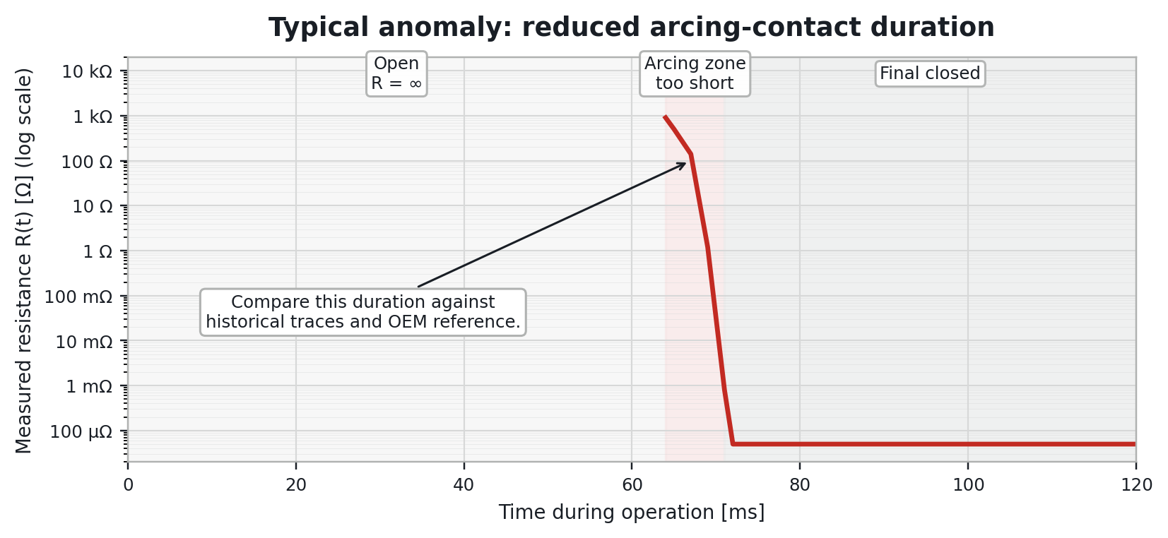
A very short arc contact conduction zone may indicate excessive wear or erosion of the arcing contact. This should be confirmed by comparing the result with historical traces, other poles of the same breaker and manufacturer references.
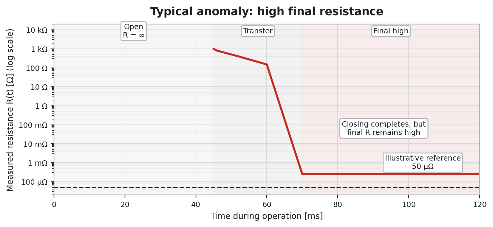
6.3 High final contact resistance
If the breaker completes the closing operation but final resistance remains higher than expected, the likely cause is related to the main contacts. Possible causes include contamination, oxidation, insufficient contact pressure, surface damage or poor test connection.
Before concluding that the breaker has an internal defect, technicians should verify the quality of clamps, current leads and Kelvin voltage measurement points.
6.4 Breakers with pre-insertion resistors
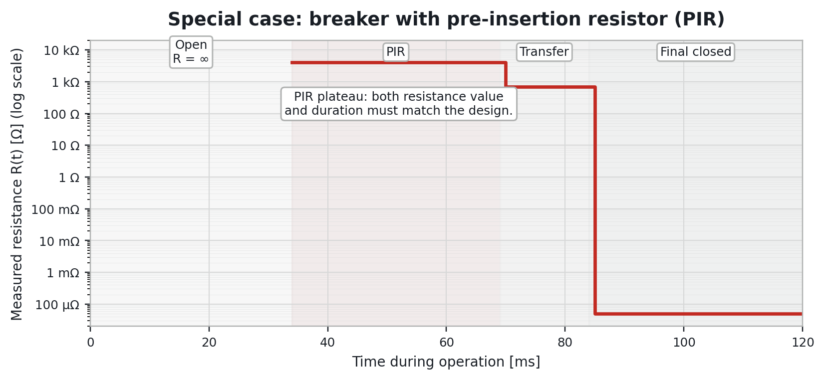
In circuit breakers equipped with pre-insertion resistors, an intermediate plateau may appear before the main contact closes. This plateau helps verify that the PIR contact operates correctly, that its duration is coherent and that the closing sequence is correct.
7. Correlation with travel, timing and synchronism
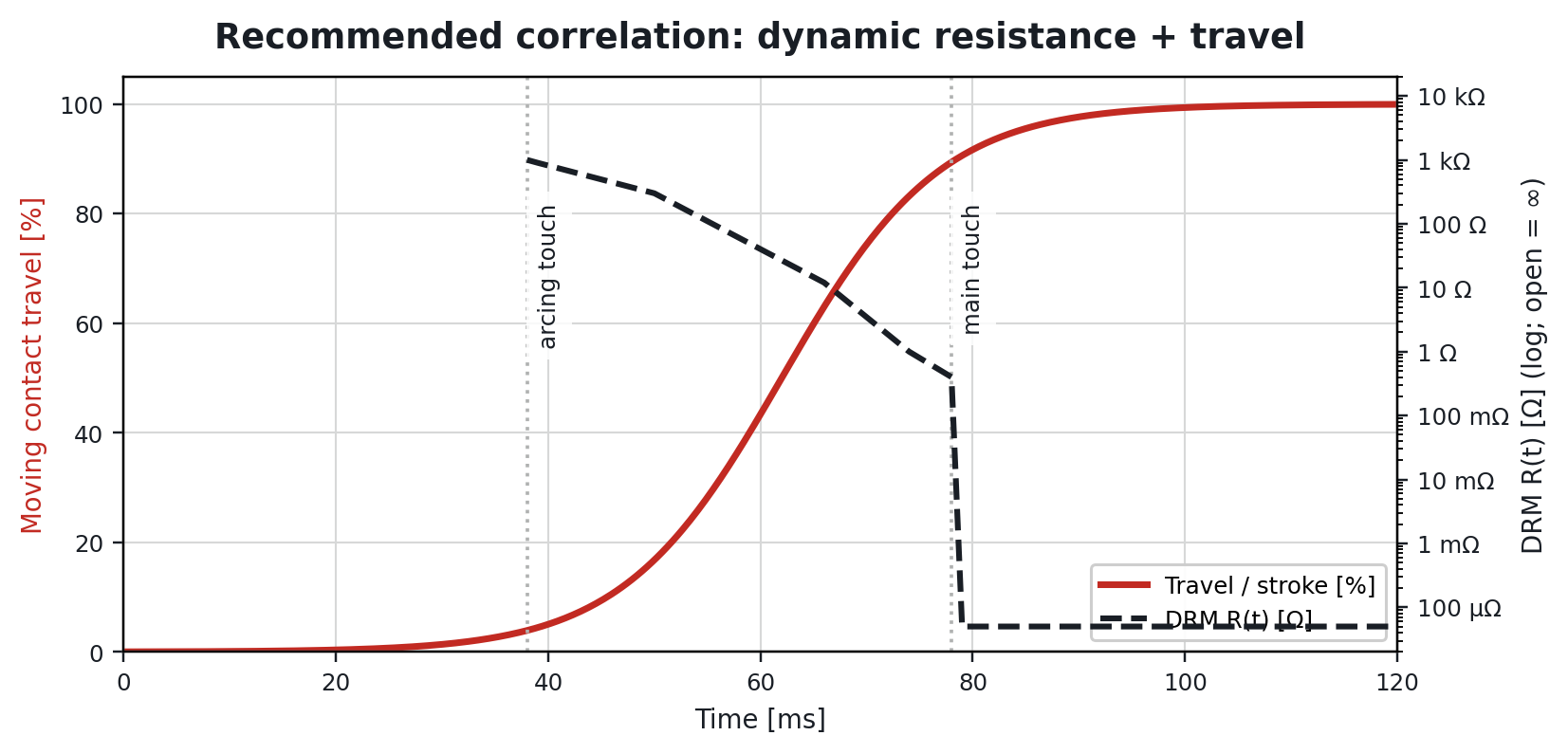
Whenever possible, DRM should be recorded together with contact travel, speed, coil timing and pole synchronism. This makes it possible to identify the exact instant of first touch, estimate arc contact conduction duration and distinguish electrical problems from mechanical problems.
During closing, this correlation is especially useful to separate a true main-contact event from noise, poor connection or contact bounce.
8. Test current and units
The DRM test is performed by injecting DC current through the circuit breaker during operation and recording voltage and current simultaneously. There is no universal current value valid for every breaker type and every method.
- 100 A DC may be sufficient for some measurements if the instrument has good resolution.
- 300 to 600 A DC may be appropriate when higher resolution is required or very low resistances are expected.
- The final test current should follow the test set manufacturer, the maintenance procedure and the breaker technology.
- Time should normally be expressed in milliseconds.
- Final contact resistance should normally be expressed in µΩ or mΩ.
- The open state should be represented as R = ∞ or out of measurable range.
9. Practical acceptance criteria
The following criteria should be used as guidance, not as universal absolute limits:
- repeatable curve over successive operations of the same pole;
- reasonable symmetry between poles of the same circuit breaker;
- clear initial drop consistent with first touch;
- transition zone without unjustified spikes, interruptions or plateaus;
- low and stable final contact resistance;
- PIR duration, where applicable, compatible with the breaker design;
- coherence between DRM curve, contact travel, coil timing, speed and synchronism;
- coherence between opening DRM and closing DRM.
10. Limitations of the test
DRM does not replace internal inspection when severe symptoms or contradictory results are present. It should not be interpreted in isolation if there are doubts about test connections, instrument saturation, electrical noise, poor repeatability or lack of historical reference.
The figures and values used in this article are illustrative. In field testing, the final diagnosis should be based on real traces, the breaker maintenance history, pole-to-pole comparison and manufacturer recommendations.
11. Conclusions
Dynamic contact resistance testing during circuit breaker closing is a powerful diagnostic method for evaluating how conduction is established in medium- and high-voltage circuit breakers. It provides information about arc contacts, main contacts, contact bounce, conduction transfer and pre-insertion resistor behavior.
Performing DRM during both opening and closing gives a more complete diagnostic picture than testing only during opening. Opening DRM shows how the contacts separate; closing DRM shows how they come together, impact, bounce and stabilize.
For reliable results, technicians should use adequate test current, verify Kelvin connections, record contact travel where possible, represent the open state correctly as R = ∞, and compare results with historical traces or manufacturer references.

