Transformer Testing Solutions
Protective relays and metering instruments in a power system rely on the proper voltage and current signals applied to them from the corresponding CT/VT/PT transformers. Therefore, a comprehensive transformer testing is carried out in factory, on site during the commissioning, and in regular maintenance throughout their service life to assure secondary circuit performance.
There are several procedures in transformer testing, with many differences and performance peculiarities, bigger in the case of power transformer testing, but there are some common routine practices mainly when testing protection and/or metering CTs/VTs, that usually covers transformer ratio, burden, polarity, phase deviation, excitation and insulation tests, among other specific transformer testing.
Description
Related Products
Additional Information about transformer testing solutions
Transformer testing with a revolutionary primary injection test system, the Raptor
When testing a CT, it is advisable to test the ratio error and phase angle at different primary currents, including at 100% of its nominal current, through high current primary injection. Besides individual transformer testing, a complete checking of the whole protective loops trough primary injection is required, combined with wire verification of the transformer circuits to ensure they are properly connected. Therefore, the need of different test sets is reduced if the high current primary testing equipment can also be used for various transformer testing tasks, combining in one system all those generic applications.
 In this sense, the Raptor is a multifunctional system that integrates the transformer testing of all kinds of CT, VT and PTs, with the high current and high voltage capability for the main primary injection applications in substations and switchgear.
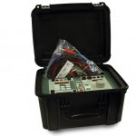
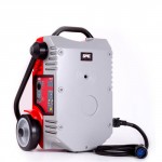
In comparison with the big and heavy traditional variac-based equipment, the RAPTOR is designed incredibly smaller and lighter than its predecessors, allowing the portability required for transformer testing; the Raptor provides a revolutionary injection technology in a really transportable test unit of only 35 Kg, which is able to inject up to 15,000 A and 2000 V. A small handheld control console allows the user to fully monitor and control all the transformer testing process.
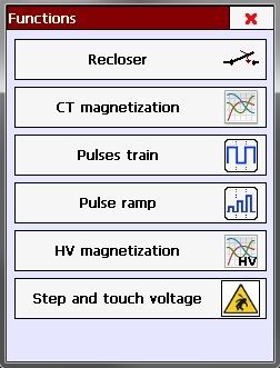
The following chart shows the different transformer testing applications included in the Raptor System:
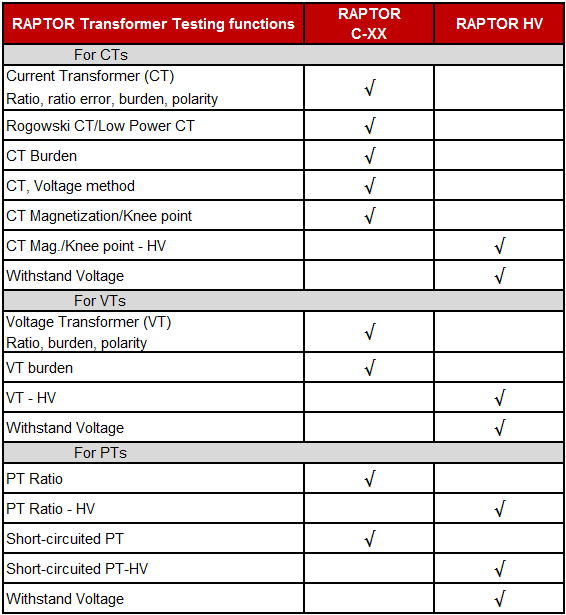

The Raptor includes transformer testing of the CT ratio through current and voltage method, being the current ratio test the preferable. If that is not possible, as in CTs situated directly in the high voltage bushings of power transformers, the ratio can be tested through voltage injection, but it should not be a substitute for current ratio test. The transformer testing at rated current offers more assurance that it will perform as expected when placed in service.
The accurate transformer testing related to burden and its power factor are important for checking if the transformer is suitable for that burden. If the CT secondary burden rating is exceeded, CT accuracy is not guaranteed. The CT burden measurement is included in Raptor from primary and from secondary side. The Raptor indicates the right or wrong CT polarity, and also the phase shift, which is very important for the downstream meters and relays.
Raptor is not only a “CT tester” but also a “VT tester”, including transformer testing functions for ratio, burden, angle/polarity, and withstand voltage in voltage transformers.
Knowing the knee transition point between normal operation and saturated region, is very important in measurement or protection CTs, and checks as well any problems with the CT. The automatic magnetization test in Raptor uses the IEC criteria for the knee point calculation, applying a logarithmic voltage ramp to the secondary winding, with the primary open, and recording applied voltage and resulting current, until the current transformer is saturated, calculating and showing the knee point, excitation curve and current. This function also performs the transformer demagnetization automatically.
The withstand voltage in transformer testing checks if the transformer dielectric strength is in suitable condition for the service, capable of withstanding overvoltages during operation. The overvoltage is applied between primary and secondary of the transformer, or between secondary and ground, being a successful transformer testing if the maximum leakage current is not reached, so that the product will be safe to use under normal operating conditions.
Other SMC solutions for transformer testing
The PME-20-PH, a digital phase angle meter, is other must-have tool that provides phase deviation on power and metering transformers. Quick phase angle measurement between two voltages, two currents or between current and voltage. Enhanced with frequency and power factor measurement.
For more information, please check the related transformer testing products or contact SMC.


For additional Information about transformer testing solutions, see the following contents
- Current Transformer Testing: Key features for suitable current transformer testing. The Raptor, current transformer testing with a multifunctional substation test system.
- Transformer Ratio Test: Transformer ratio test in power and instrument transformers, different solutions and methods.
- Transformer Turns Ratio: Transformer turns ratio in power and instrument transformers, different testing solutions and methods.