Transformer Turns Ratio
The transformer turns ratio is the number of turns of the primary winding divided by the number of turns of the secondary coil. The transformer turns ratio provides the expected operation of the transformer and the corresponding voltage required on the secondary winding.
If it is required a secondary voltage smaller than the primary voltage – step-down transformer- the number of turns on the secondary must be lower than in primary, and for step-up transformers is the other way round; when the transformer turns ratio step-down the voltage, it steps-up the current and vice versa, so that the voltage and current ratio of an ideal transformer is directly related to the turns ratio.
The transformer turns ratio in real transformers
Unfortunately, transformers are not ideal, and in a real transformer the voltage or current ratio may be not equal to the physical transformer turns ratio, due to the different electrical losses such as in the transformer iron core (hysteresis and eddy current losses) and copper losses (due to the electrical resistance of the primary and secondary windings); therefore, the manufacturers try to design the transformers in a way that minimize those losses, for getting a maximum efficiency at full load, higher to 95% of power transformation, and thus providing a voltage ratio which differs as maximum in 5% to the transformer turns ratio.
But since the transformers suffers different stresses and changes in their life, electrical and mechanical, the proper transformer turns ratio must be verified before placing it in service and during the different maintenance schedules, which is the target of the transformer turns ratio testers; therefore, the ratio measured with the different transformer turns ratio test sets (TTR equipment) includes the losses normally found in the transformer, which result in a ratio different to the physical turns but reflects the real voltage ratio expected by the manufacturer and the user, or the true electrical transformer turns ratio.
Transformer turns ratio in power and instrument transformers, different testing solutions and methods
The transformer turns ratio test helps to identify problems such as shorted-turns or open-turns, incorrect connections, tap changer and internal magnetic core problems, etc; the different transformer turns ratio test sets are specifically designed for the application depending on the type of transformer and the ratio to measure.
In power transformers the transformer turns ratio test is made through voltage injection, phase by phase and tap by tap, measuring the corresponding voltage ratio for the related windings, which is compared with the expected ratio of the nameplate.
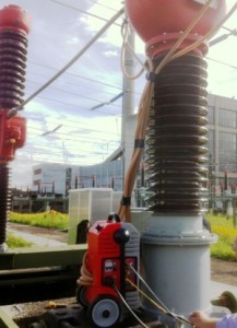
In the case of the current transformers for instrumentation, the transformer turns ratio is defined as a ratio of the rated primary current to the rated secondary current at specified burden, so that a different injection range and type is required in the suitable current transformer turns ratio test sets; those must provide the high rated currents required and must have a high power to meet the different testing situations; the power required for the same nominal current range will not be the same whether the transformer is close or situated very high at a distance of many meters.

Fortunately, the small size and weight of the Raptor System allows it to be placed closer to the transformer under test and reduce the test leads length and the power required; furthermore, the modularity of the Raptor provides the capacity to increase the power of the system, when required, adding current slave units, in a very simple and quick way, thanks to the self-detecting infrared technology and the no need to interconnect the units; up to three slaves can be added for up to 15,000 A and up to 18-kVA total injection power, to cover the different situations in transformer turns ratio testing.
The Raptor System provides several test templates and functions for transformer turns ratio measurement in current transformers, voltage transformers and power transformers, with the required current and voltage injection and corresponding integrated measurement capability. The current transformer turns ratio test can be performed through current or voltage injection, being always preferable the current method, but the Raptor includes both for those cases in which is not possible to inject primary current in the CT; the Raptor also includes templates for the current transformer turns ratio of Rogowski and low power CTs; the VT and PT ratio is performed through voltage injection, which range is extended if the system is complemented with the optional Raptor high voltage slave.
The Raptor is a multifunctional substation test system, including transformer tests for the ratio, burden, polarity, knee point and withstand voltage, and many other primary injection applications for testing breakers, reclosers, relays, ground grid, resistance, etc.
As usual with SMC test equipment, simplicity and ease-of-use are common to all solutions for transformer turns ratio tests.
For more information, please check the related SMC products or contact us.
