Understanding the Heat Run Test with Primary Current Injection
What a Heat Run (Temperature-Rise) Test Proves and Why It Matters
A heat run test—also called a temperature-rise test—verifies that equipment runs within safe thermal limits under rated or near-rated load for an extended time. You circulate a controlled current through the full primary path and monitor temperature rise at hot-spot locations. This exposes loose joints, high-resistance contacts, undersized conductors, poor ventilation, or flawed assembly that can lead to overheating and failures. Authoritative descriptions align on this purpose across technical sources for transformers and switchgear.

Where it applies: low-voltage and medium-voltage switchgear, busbars, circuit breakers, connections, and current transformers. The goal is thermal stability at steady state with temperature rises within accepted limits.
Primary Current Injection vs Secondary Injection: when to use each
Primary current injection drives high current through the entire primary path. It validates the full current-carrying chain and thermal behavior under realistic loading. Secondary injection stimulates only the relay or trip unit logic and associated secondary wiring. Use secondary for fast functional checks, but rely on primary when you need to verify the whole path and heat performance.
Equipment: choosing a high current test set and sensors
A high current test set must deliver the target current for long enough to reach thermal steady state, with enough compliance voltage to overcome the load impedance and cable drops. Typical sensors are thermocouples for point measurements and infrared thermography for hot-spot scanning.
Sizing the test set: current, duty cycle, compliance voltage
Check rated current and expected duration to steady state. Ensure the source can maintain current without sag. Systems designed for primary injection on switchgear often provide modular power and techniques to increase effective compliance, which is key when busbar lengths, multiple leads, or extra turns raise impedance.
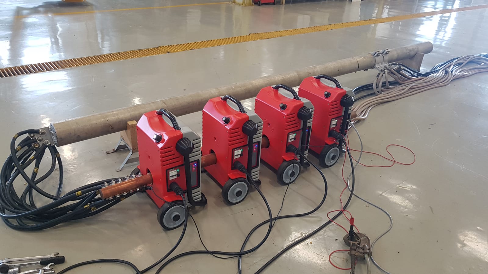
Example high current test set: EuroSMC RAPTOR
The RAPTOR primary test system is a compact, modular high current test set. It combines a master unit with optional slave units to increase power. It supports a pass-through technique using the central aperture, allows multiple cable passes to increase effective compliance voltage, and can be expanded up to high-current ranges suitable for heat runs on switchgear and busbars. Configurations scale power from about 3 kVA upward, with injection capabilities into thousands of amperes for thermal testing.
Thermocouples and IR for hot-spot detection
Use K-type thermocouples on busbar joints, breaker terminals, and cable lugs. Sweep with an IR camera to catch non-obvious hot-spots around shields, barriers, and cable terminations.
Step-by-step heat run test procedure
Setup and safety checks
-
De-energize, lock-out/tag-out, and install barriers.
-
Inspect all primary connections. Clean and torque per manufacturer.
-
Place thermocouples at: incoming/outgoing lugs, busbar joints, breaker line/load, neutral links, CT terminals. Mark ambient reference.
-
Prepare the RAPTOR with adequate cross-section leads. If distance or impedance is high, add slave units or use additional passes through the aperture to increase compliance voltage.
Current ramp and steady-state criteria
-
Ramp from ~50% to target current while watching early hot-spots.
-
Hold the heat run until temperature slope flattens (steady state). Duration ranges from tens of minutes to hours depending on mass and airflow. Technical references describe maintaining rated current until stable temperature is reached.
Voltage-drop checks across joints
Measure mV drop across each critical joint at constant current. High or asymmetric drops indicate resistive connections that will overheat under load.
Interpreting results against acceptance criteria
Compare hot-spot rises against your specification or applicable standards for switchgear and breakers. Practical guidance from industry sources frames temperature-rise limits and steady-state verification as core acceptance logic for heat runs.
Corrective actions and re-test
If limits are exceeded:
-
Re-torque, clean or replace contacts; upgrade lug cross-section; improve ventilation.
-
Reduce impedance by shortening cables or increasing cross-section; if needed, increase RAPTOR power or passes to maintain target current during re-test.
Common pitfalls: cable length, turns, and load balancing
-
Long leads or small cross-section raise impedance. Add power or increase passes through the RAPTOR aperture to multiply effective compliance voltage.
-
Unbalanced outgoers in assemblies skew heating. Balance currents to represent worst-case diversity where required.
-
Sensor placement too sparse misses hot joints. Always instrument both sides of bolted joints.
FAQs: heat run testing and primary injection
How long to reach steady state? Until the temperature-time curve flattens at critical points. Expect 30–180 minutes depending on mass and cooling.
What current level is typical? Rated operational current or a defined fraction that yields representative heating without exceeding limits.
Why primary instead of secondary? Only primary validates the full thermal path and real conductors under load; secondary validates logic only.
Is the RAPTOR suitable for heat runs? Yes. It supports heat runs and offers pass-through plus modular expansion for high current and higher compliance voltage.