Dynamic Resistance Measurements on SF6 circuit breakers using Micro ohmmeter tester
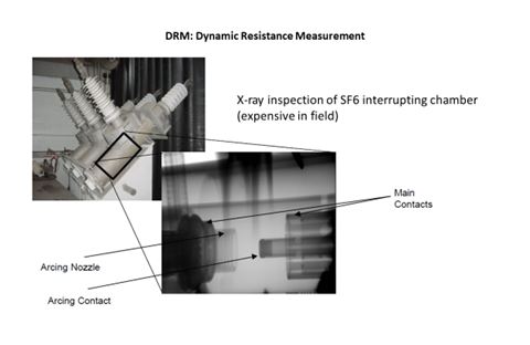
Knowing the condition of SF6 circuit breaker contacts presents some problems. They cannot be seen without disassembly of the contact housing or X-Raying them. A contact resistance measurement using a Micro ohmmeter does not give the whole picture since the resistance obtained is the combination of the main contact and the arcing contact together. That result is nearly always good because the main contact is not the one that takes most of the abuse but does carry the most load and therefore has the lower resistance. Most of the failures of SF6 circuit breakers is due to the poor condition of the arcing contact as they are designed to take the abuse during a fault. The cost of X-raying the contacts is quite high so most SF6 circuit breakers are simply put on a maintenance schedule. This means that some SF6 circuit breakers are serviced unnecessarily while some need service earlier than scheduled.
The best solution would be to be able to evaluate the condition of the arcing contact independently from the main contact without disassembly or X-rays. Well this can be done with a Dynamic Resistance Measurement (DRM). A DRM is simply the resistance measurement over time as the circuit breaker opens. By doing the DRM the resistance of the main contact plus the arcing contact can be separated from the arcing contact alone. There are circuit breaker analyzers that can perform the DRM but it is often a complicated and time consuming setup.
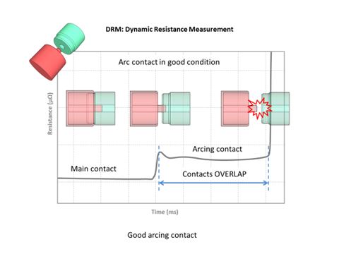
A Micro ohmmeter tester such as the Prime600 micro-ohmmeter that can perform the DRM with the same setup as a simple contact resistance measurement is ideal. Above a DRM of a good arcing contact is shown. Notice the smooth graph representing the resistance vs time of the arcing contact as the circuit breaker opens.
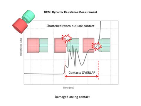
The graph of the damaged arcing contact shows resistance spikes that represent melted or damaged spots on the arcing contact. Although this is not a definitive test that says this circuit breaker is bad; it does give the maintenance engineer information with which he can make a more informed decision as to when to take this circuit breaker out of service for maintenance.
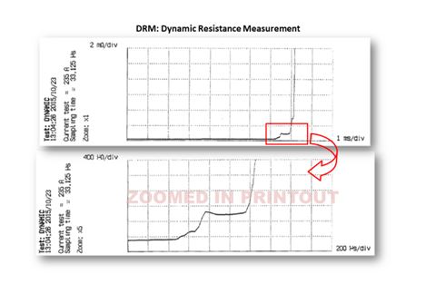
Below is a typical graph produced by the Prime600 Micro ohmmeter tester
In summary the information that can be gained by testing SF6 circuit breakers with the doctor tester Prime600 is as follows:
- Resistance of the main and arcing contacts combined.
- Length of the arcing contact
- Condition of the arcing contact
- Total operating time of the circuit breaker
- A graph of the resistance vs time
All this information can be obtained by using a Prime600 micro-ohmmeter when Micro ohmmeter is used anyway to obtain the static contact resistance.
Having this additional information allows the maintenance engineer to make an educated decision concerning when to schedule service on SF6 breakers.
About Micro Ohmmeters
Micro ohmmeters work by injecting very high test currents through a conductor in order to measure extremely low resistances with excellent accuracy and resolution. This has practical applications for testing contact resistance in switches, bonds and circuit breakers.
Micro ohmmeter Testing: Working Principle and Applications
Micro ohmmeter testing, also known as contact resistance test, measures the resistance of electrical connections – terminations, joints, connectors and so on. These can be connections between any two conductors, for example, cable connections or busbar sections. The instrument which is used to perform the Micro ohmmeter test is called an Ohmmeter, and since its function is to perform the Micro ohmmeter test, the ohmmeter is also known as a Micro ohmmeter tester.
The Micro ohmmeter tester can be found in many variations such as Micro, Mega and Milli- Ohmmeters, used to measure resistance in different applications of electrical testing.
There are two types of Micro ohmmeter testers in general:
- Series Type Ohmmeter has 4 resistors, internal battery voltage – E, and output terminals, A and B. When connected the A and B terminals with the R1 and R2 resistors, the battery forms a simple series circuit.
- Shunt Type Ohmmeter, used for measuring small values of current resistance. When the A and B terminals are closed, the needle reads zero because the current flows only through the resistor RX. When these two terminals are opened, there is no current flowing through the RX resistor, thus the reading on the Micro ohmmeter tester is marked as infinite.
Micro ohmmeter testing is used to verify that electrical connections are made properly and it has been designed to detect problems such as:
- Corroded contacts
- Loose connections
- Adequate tension on bolted joints
- Eroded contact surfaces
This test is especially important for contacts that carry large amounts of current because higher contact resistance can lead to lower current carrying capacity and higher losses. Micro ohmmeter testing is usually performed using a micro/milli-ohmmeter or low ohmmeter.
Micro ohmmeter Test Criteria
The criteria for evaluating the contact resistance depends on the metallic surface area, the contact pressure, the type of connection (ex. soldered, bolted, clamped, welded, etc.) and so on.