Electrical Panel Test
The electrical panels, widely used in all kind of substations and industrial applications, integrates all the secondary devices, such as the measurement elements, control switches, signaling and secondary protections (overcurrent, distance, voltage relays, etc). The electrical panel test in any power system is made to ensure that the panel construction, connection and performance is correct from the operational, reliability and safety viewpoint; hence, to ensure the continuity of electrical operation, a comprehensive panel test is carried out in factory, in commissioning and during maintenance programs, with many different inspection, quality and panel test procedures.
A suitable panel test requires having the right test devices to ensure a better and quicker work, which must have the proper flexibility to adapt to the different situations during the panel test; since 1986, EuroSMC is offering distinctive electrical panel test tools which are addressed to the user and the application, with a wide range of options to fit every need.
Key procedures in the panel test and related test sets
Two of the main targets in any panel test are the checking of the secondary protections and all the associated wiring and signals of the whole protection system, being essential to carry out functional performance tests for finding reliability deficiencies before any problem happens. Some electrical panel test procedures for ensuring the effectiveness of the different elements in the panel and their joint operation are the following:
More infoRelay tests
As a main protection element, the testing of the relay performance and settings is always included in any panel test; the different relay types, relay generation and specific protection functions will define the suitable relay test set.

When the panel test requires a quick and simple checking of some single-phase overcurrent and voltage protections, the multipurpose PTE-100-C is a proven and reliable equipment, used daily worldwide, that combines the power, portability, and measuring capacity, with the simplicity of operation required. The unit can be upgraded at any time to the Plus/Pro version, adding an independent voltage channel with phase shifter and frequency generator, extending the testable functions to those for directional, distance, frequency, synchronization relays, etc.
The digital single phase units of the PTE range (PTE-50-CE, PTE-100-V, UNO) are other option with the same straightforward use philosophy and portability, which also provides higher accuracy and stability in the panel test, with fault dynamic testing and great flexibility thanks to their reversible current/voltage channels and interconnection capability with any other unit; for example, they can be connected to the 3-phase units of the PTE range (PTE-50-CET or PTE-300-V) for increasing the required testing applications.
The Mentor fulfills the flexibility requirements in any electrical panel test, a single-box solution, independent of PC, for testing all types of relays and protection schemes. The modularity of the Mentor allows multiple configurations, from the classic 3V3I (3 Voltages- 3 Currents – with 6 currents available) up to the maximum of 6V6I (two 3-phase systems in one unit, suitable for end-to-end testing), and it is perfectly suited for relay testing, with a big sized screen that allows continuous graphic and visual monitoring of the panel test process, and the quickest and most complete manual control. The Mentor integrates many useful test functions for the panel test, without the need of external PC, such as State Sequencer, Fault, Ramps, Pulse Ramps, Binary Search, COMTRADE playback, and direct regulation of complex magnitudes (impedance, power, symmetrical components, homopolar Voltage, etc).
More infoSecondary injection tests
The electrical panel test also involves checking all the wiring and signals to the relays and instruments, for the proper operation of the protection logic and the measuring reliability. The continuity and operation of the protection and control circuits during the panel test is a key factor in the security. Point-to-point checks of wiring through secondary injection is usual in the panel test procedures, and any of the mentioned secondary injection test sets can be used as current or voltage sources to perform verification of the different control, signaling and tripping circuits, through generation of nominal and fault values.
All terminals must also be checked for receiving the signals with the correct angle, for which the digital phase angle meter PME-20-PH is a useful tool in the panel test.
Similarly to the commented electrical continuity, the GOOSEMeter checks the correct continuity of the broadcast GOOSE messages in the IEC 61850 based networks, as a bridge between the code and the power world in this type of electrical panel test.
Scheme tests
For verification of the tripping scheme, the panel test procedure may include the simulation of protection sequences, for which the easy to program state sequencer included in the Mentor 12 is an invaluable tool which does not require the use of PC, and can also include GPS timed sequences. The ROOTS (Relay Object‐Oriented Test System) is a powerful automation software, which includes pre-programmed scheme tests, oriented to specific protection modules, such as reclose functions, circuit breaker failure, fuse fail, etc.
More infoPrimary injection tests
Elements such as MCBs and MMCBs may require in the panel test of higher currents than the range provided by the secondary injection test sets, for which any of the LET range or any of the Raptor configurations are suitable as high current source for magnetic and shortcircuit trip tests; likewise, the same equipment can be used for the whole panel performance through a primary injection test; the panel test may include the heating verification under long-term current conditions, for which the Raptor is very suitable because of its stability throughout the injection time; now the optional HV unit provides also the capacity to perform dielectric strength checks up to 2000 V, to those elements that must keep insulation integrity in the panel test.
Contact resistance tests
Other typical task in the panel test is to perform contact resistance test in all bus joints and critical connections, to avoid higher resistance paths and dangerous hot spots. EuroSMC offers different microhmeters for this purpose, but we highlight our new PRIME 600, that provides pure DC, which becomes important when checking a whole bus bar and the resistance measurement could be affected by the nature of the DC injected.
Polarity tests
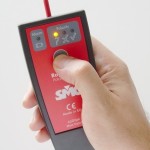
 A reversed polarity may cause the protection does not work or be unstable; the PME-20-PH can be used for polarity testing in combination with any of the secondary injection test units; the Raptor Polarity Tester provides a more straightforward and efficient checking of the polarity in the panel test, with an special waveform generated by the Raptor at the beginning of the circuit, which is comfortably traced downstream by the small handheld Polarity tester.
For more information, please check the related EuroSMC products or contact us.
